![]()
Pintsch Bubenzer - industrial brakes for port cranes, windmills, and industrial lifting equipment
Bubenzer originally made high performance disc and drum brakes for port cranes and other severe duty applications, as well as complementary goods, like emergency brakes and storm brakes. The company has also successfully marketed the same braking concept to the industrial crane and windmill sectors. In many cases, their product is requested as single-source in specification documents.
Contact
Bartles Corner Business Park
8 Bartles Corner Road, Suite 102
Flemington, NJ, 08822
Joel Cox
t: +1-908-237-9400
e: j.cox@pintschbubenzerusa.com
w: www.pintschbubenzerusa.com
Pintsch Bubenzer Highlights Torque Loss During Movable Bridge Rotations
Pintsch Bubenzer USA is raising awareness about the torque that is lost as movable bridges are raised, typically up to 70°, and the advantages of disc versus shoe (drum) brakes.
Pintsch Bubenzer, which makes high performance disc and drum brakes for severe duty applications, continues to give presentations to architectural and engineering professionals in the infrastructure sector about the significant loss of torque that some brakes experience as bridges are raised and lowered—losses that should be accounted for during the initial design of a bridge.
It is called rotational torque loss because the machinery (motor, gearbox and brake) physically rotates with the bridge. When the bridge is closed the machinery is in the horizontal position; as the bridge opens, the machinery rotates with the structure. On the majority of the bridges where the brakes rotate, the bridge opens in the center. These types of bridges are called bascule or rolling bascule bridges. However, a bascule bridge can be either a single leaf type (opens at one end) or a double leaf type (opens in the center).
A typical movable bridge contains two sets of brakes called motor brakes and machinery brakes. The motor brakes are connected to the high speed shaft of the electric motor; the machinery brakes are located on the output shaft of the secondary gearbox (also called a reducer).
The brakes are designed to hold the bridge in either the open or closed position. They take into account wind loading or ice build-up that may occur so as not to allow the bridge to drop when it is in the open position. The electrical controls are primarily responsible for bringing the bridge to a complete stop, while the brakes are applied right after the bridge stops and are primarily used as a holding mechanism. The number of brakes and the size are dependent on the machinery design of the bridge.
Mike Astemborski, executive sales manager—movable bridge market at Pintsch Bubenzer USA, said: “Many engineers are surprised just how great the torque loss can be; on a drum brake we can be talking about a 25% loss. During the rotation of the bridge and the machinery the center of gravity is changing. There is no physical impact on the brake but mechanically there is a slight shifting of the mechanical components—thruster, levers, brake arms and brake shoes—that affect the torque of the brake.”
Astemborski explained that when the company performs educational sessions to architectural and engineering firms, the content explores four main areas: torque loss on shoe brakes during rotation; torque loss comparison between a disc brake and a shoe brake; loss of friction when using chrome-plated brake wheels; and loss of friction when using stainless steel brake wheels. As an example, when using chrome-plated brake wheels, the co-efficient of friction is reduced from 0.4 to 0.33, which equates to a 17.5% reduction in brake torque.
Pintsch Bubenzer is of the opinion that the disc brake is the better option to reduce the amount of torque loss. Testing has shown that the disc brake produces less than 4% torque loss due to its mechanical configuration. In addition, the disc brakes are supplied with a sintered lining material, which is a huge advantage over the molded lining material of a shoe brake due to a heat dissipating characteristic.
Astemborski said: “We support our presentations and literature with science and fact; our colleagues in Germany designed a rotational test bench that simulated the opening and closing of a movable bridge in 10° increments.”
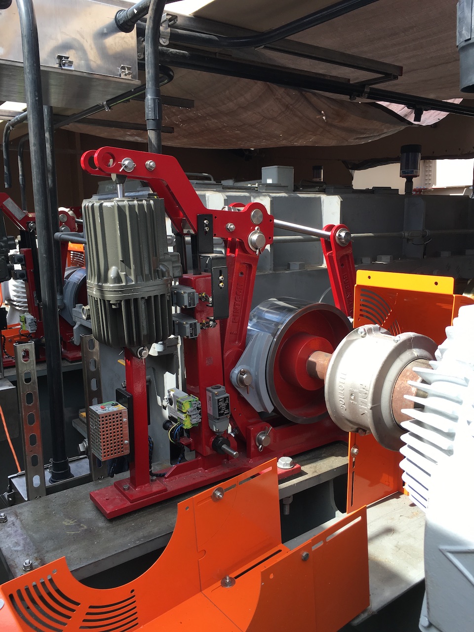
Caption: Motor brakes are connected to the high speed shaft of the electric motor.
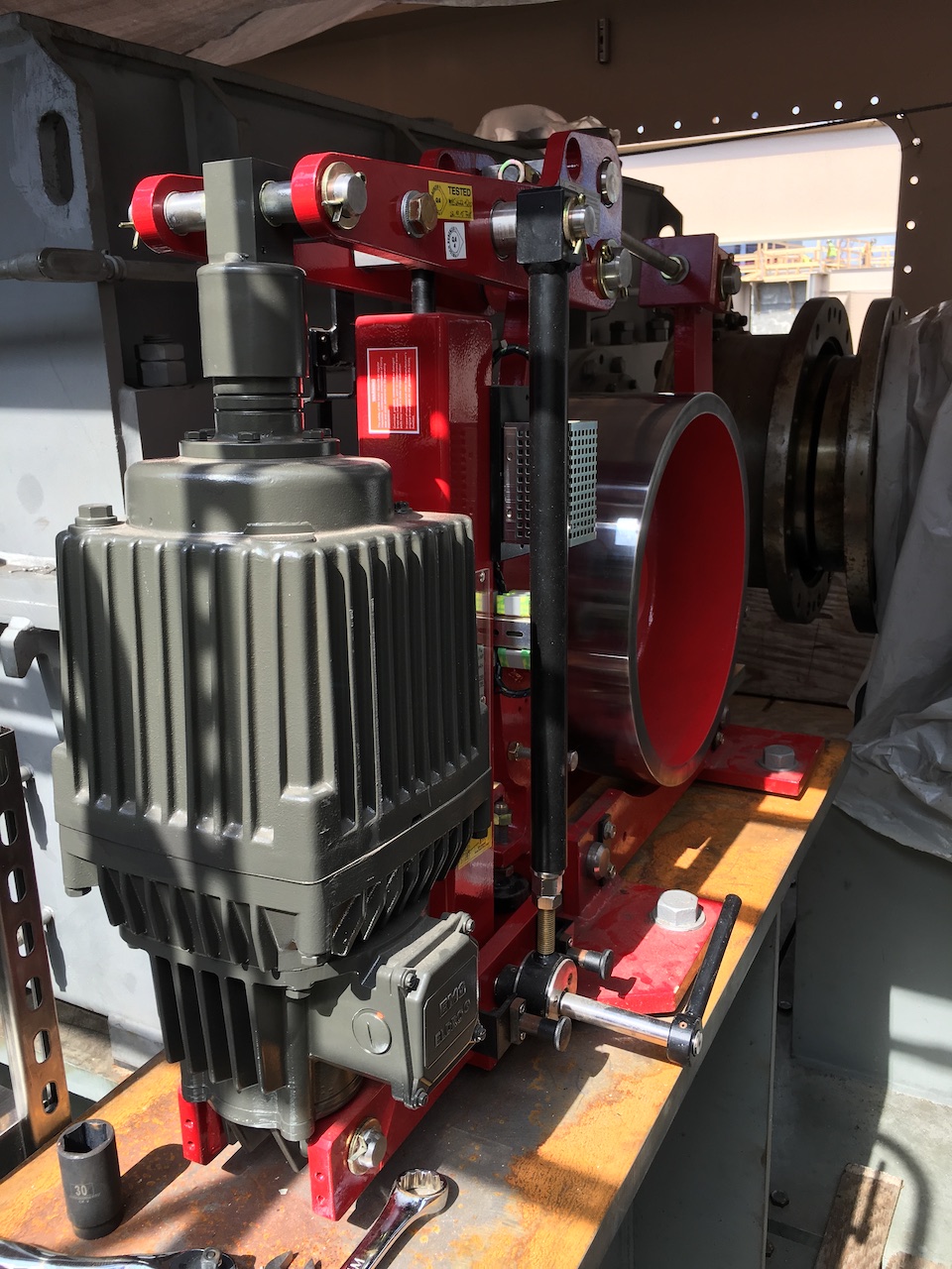
Caption: Machinery brakes are located on the output shaft of the secondary gearbox (also called a reducer).
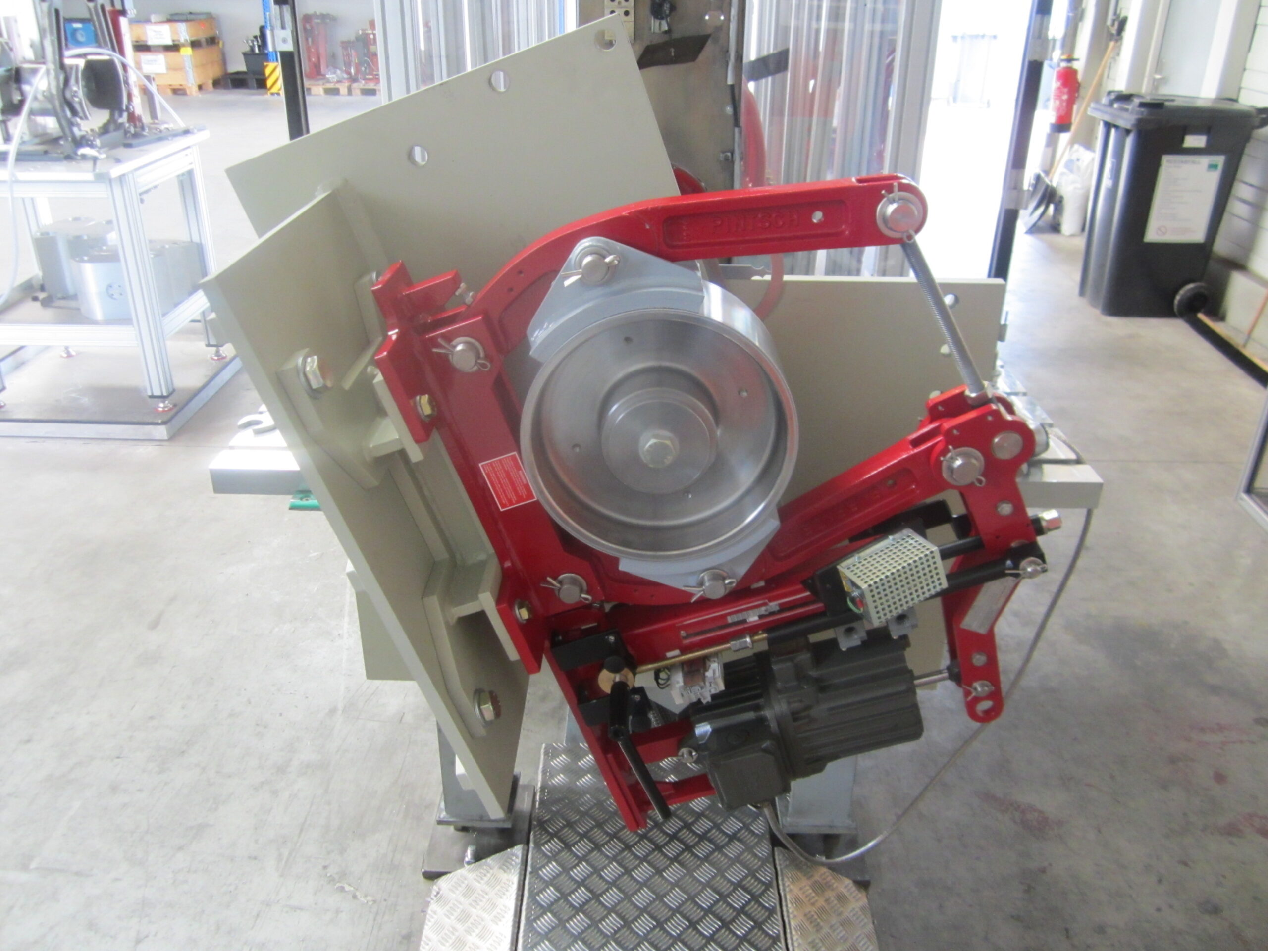
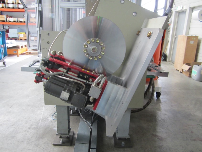
Caption: Shoe brake rotational testing.
Contact for editorial enquiries: Joel Cox, j.cox@pintschbubenzerusa.com


