
Casper, Phillips & Associates - Globally Recognised Crane Engineering Services
Casper, Phillips & Associates Inc. (CPA) offers crane engineering, structural engineering, custom software and other specialist services, for ports and heavy-duty environments. CPA offers a wide variety of services tailored to customers’ needs, including procurement, specification, design, voyage bracing, modifications and rehabilitation, accident investigation and repair, and condition surveys.
With crane and material handling equipment design experience dating back to the 1960s, it can provide this service with speed and efficiency. In crane and load handling equipment, much of CPA’s practice is devoted to helping buyers contract for the machinery they want to own and then assist in enforcing the contract’s technical requirements so the buyer gets what the contract stipulates is to be provided.
Among CPA’s portfolio is a patented crane base anti-seismic isolation system (BASIS), created with nonlinear time history analysis (NLTHA).
Contact
Richie Philips
t: +1253 627-7400
e: casperph@cranedesign.com
w: www.casperphillips.com
LATEST NEWS
Industry’s Bottom Dollar
Choosing lifting equipment should never come down to price alone, but it remains very common to accept the lowest bid. While cost should be considered, it must be weighed against other aspects of procurement, says Richard Phillips, mechanical engineer at Casper, Phillips & Associates Inc.
As the crane industry rallies around the theme for this year’s Global Lifting Awareness Day (GLAD) — ‘Not all lifting equipment is created equal’ — it’s worth reminding all stakeholders of the risks involved with short-sighted procurement.
On July 2, 2026, the Lifting Equipment Engineers Association (LEEA), the force behind GLAD, will publish a guidance document that procurement professionals can use to source lifting equipment. The emerging body of work is likely exposing a stark reality: the strapline underpinning this year’s campaign remains necessary because certain sectors continue to assume that all lifting equipment is created equal, conflating lowest cost with fitness for purpose.
CP&A offers a wide variety of services, including specification, design, manufacturing review, modification, and accident investigation, meaning I’ve spent many years in procurement, design, design review, and repair of cranes. I continue to go from client-to-client, solving complex material handling problems, often met with the naive assumption that buying lifting equipment, even hulking container cranes, is the same as buying any other piece of equipment such as a forklift or a company van. In reality, lifting equipment sits in a fundamentally different category, where specification, duty cycle, and risk profile must be engineered into the procurement decision from the outset.
A good starting point is the concept of crane classes, such as those published by the MHI’s Crane Manufacturers Association of America (CMAA). In simple terms, cranes are classified according to their intended duty, and that classification is embedded in the purchase specification. A standby crane used for infrequent lifts does not need to be designed to the same standards as one operating three shifts a day, constantly handling loads near its rated capacity. The latter must be significantly more robust, with far greater attention paid to fatigue life and component reliability to minimize downtime. There are, of course, classes in between, but this contrast serves well to illustrate the principle.
This becomes even clearer when things go wrong. Say, a chain hoist failed under sustained load at approximately half its rated capacity. The cause might be stress corrosion cracking driven by hydrogen embrittlement, which is a known vulnerability in certain chain used in corrosive environments. The chain might have been selected based on its Working Load Limit (WLL) — and price — but no consideration was given to the environmental conditions in which the chain grade’s protection would deteriorate, nor to the manufacturer’s guidance discouraging sustained loading.
Reference framework
CMAA’s classifications should not be viewed as definitive or universally prescriptive. Rather, they provide a widely recognized and relatively straightforward reference framework for describing crane duty and application. In Europe, for example, the industry is increasingly aligned with EN 13001 under the Machinery Directive, which approaches design and classification through a broader, more formalized safety and engineering standard. While most international codes adopt the underlying principle of categorizing cranes according to duty and intensity of use, the way those principles are expressed, calculated, and enforced can vary significantly between regions. As a result, classification systems should be understood as tools for engineering judgment and communication, rather than interchangeable rulesets that guarantee equivalence across standards.
We work across multiple crane sectors, which gives us exposure to a wide range of design philosophies and engineering conventions. This is particularly relevant when comparing how duty classification is applied in different industries. In the overhead crane sector, the use of formal crane classes is especially prevalent and more finely differentiated, reflecting the diversity of applications they serve.
For example, within the CMAA framework, container handling applications are typically aligned with Class E service, indicating severe duty operation with high utilization and demanding load profiles. As a result, container cranes are generally regarded as inherently heavy-duty assets by design and expectation. By contrast, overhead cranes span a much broader spectrum of use cases, ranging from light-duty workshop applications through to continuous production environments, and are therefore classified anywhere from Class A to Class F depending on intensity, frequency, and loading conditions.
The good news is that the message, ‘Not all lifting equipment is created equal’, is beginning to gain traction in certain markets and applications. Bearings provide a useful illustration. These seemingly small mechanical components are fundamental to crane operation and are typically rated according to expected hours of service. Under CMAA classifications, a Class A standby crane intended for infrequent use requires bearings with a minimum design life of 1,250 hours. By contrast, Class E severe-duty cranes require a minimum design life of 40,000 hours, and it is not uncommon for performance specifications on heavily utilised cranes to push that requirement to 50,000 hours or more. While bearings are only one component among many, they clearly demonstrate how crane classification directly influences engineering assumptions around maintenance intervals, durability, and lifecycle performance.
Container cranes provide an even more striking example of how duty classification shapes specification. A ship-to-shore crane may operate continuously on a 24-hour basis, placing enormous demands on its primary power transmission systems, including the main hoist, trolley, gantry, and boom hoist mechanisms. These systems are therefore typically designed to CMAA Class E service, where minimizing maintenance and avoiding unplanned downtime are operational imperatives. Yet within the same crane structure sit smaller maintenance cranes housed inside the machinery room, used only occasionally to lift heavy components between the ground and the machinery house — tasks such as transporting a 500-lb. (225 kg) drum up to a structure that may stand 200ft (60m) tall. Because these cranes might only operate for a few hours each month, their classifications can range from Class A through to Class C. Suddenly, the difference between a bearing designed for 1,250 hours and one designed for 50,000 hours becomes entirely logical.
The application, duty cycle, and operational consequences of downtime (not simply lifting capacity) are thusly what ultimately determine the appropriate specification.
Go above and beyond the call of duty
Crane specification is also shaped by a range of environmental and regulatory considerations that extend beyond basic duty classification. Factors such as indoor versus outdoor installation, enclosure class requirements, and protective paint systems all play a critical role in ensuring long-term performance and reliability. For outdoor applications in particular, design must account for wind loading and potentially wider ambient temperature ranges, while coating systems need to be specified with sufficient durability to withstand corrosion and environmental exposure over the equipment’s service life. In more specialized applications, such as aerospace-grade areas, these considerations become even more stringent, with heightened expectations around environmental resistance and material performance. One set of cranes designed by CP&A could not contain any silicone because silicone interferes with the painting process of the assemblies the cranes operated on.
At the higher end of the safety spectrum, concepts such as single failure proof design are employed, particularly in industries like nuclear and aerospace. These cranes are engineered with redundant load paths so that the failure of any single component does not result in load drop or loss of control. A related concept, fracture critical member design, was later introduced into the container crane industry, drawing on principles originally developed by the Federal Highway Administration. While similar in intent, focusing on preventing catastrophic failure through structural integrity, fracture critical design places greater emphasis on the structural elements of the crane, with comparatively less focus on mechanical, electrical, or control system redundancy.
In conclusion, procurement plays a far greater role in safety outcomes than is often recognized. The selection of lifting equipment should never be reduced to a simple cost comparison; it is fundamentally a judgment about fitness for purpose. That decision must account for the specific task the equipment is intended to perform, the environmental conditions it will be exposed to, and the applicable design and regulatory standards that govern its use. Equally important is an accurate interpretation of what the manufacturer’s documentation actually states — and, just as critically, what it does not state — about those conditions and limitations.
When these factors are not fully understood or properly weighed, procurement decisions risk embedding assumptions that only become visible once the equipment is in service. In that sense, the act of specification is not administrative but integral to safety engineering itself, shaping performance, reliability, and ultimately operational risk from the outset.
- Global Lifting Awareness Day (GLAD) 2026 takes place on Thursday July 2, 2026. The seventh staging of the event, powered by the Lifting Equipment Engineers Association (LEEA), its members and supporting industry stakeholders, will culminate in publication of a guidance document that procurement professionals can use to source lifting equipment.
<in a box>
BASIS for non-price-driven procurement
Nowhere are crane classifications and specification requirements more critical than in environments exposed to frequent seismic and contingency-level earthquake activity. In these regions, cranes are not simply evaluated on duty cycle or lifting capacity alone, but on their ability to maintain structural integrity and operational safety under dynamic, unpredictable loading conditions.
Our crane base anti-seismic isolation system (BASIS) is built on nonlinear time history analysis (NLTHA) and can protect the crane main structure from damage even in contingency-level earthquakes. BASIS is installed between the sill beam and main equalizer beam, about 13 ft. (4m) to 16 ft. (5m) from ground level depending on the crane’s size. It includes two friction damper assemblies, two energy restoring device assemblies, a guiding device, and two friction damper locking devices. Typically, ports specify the seismic requirements, while the crane manufacturers propose the isolation system. The port then makes the final decision on the proposed purchase.
<end box>
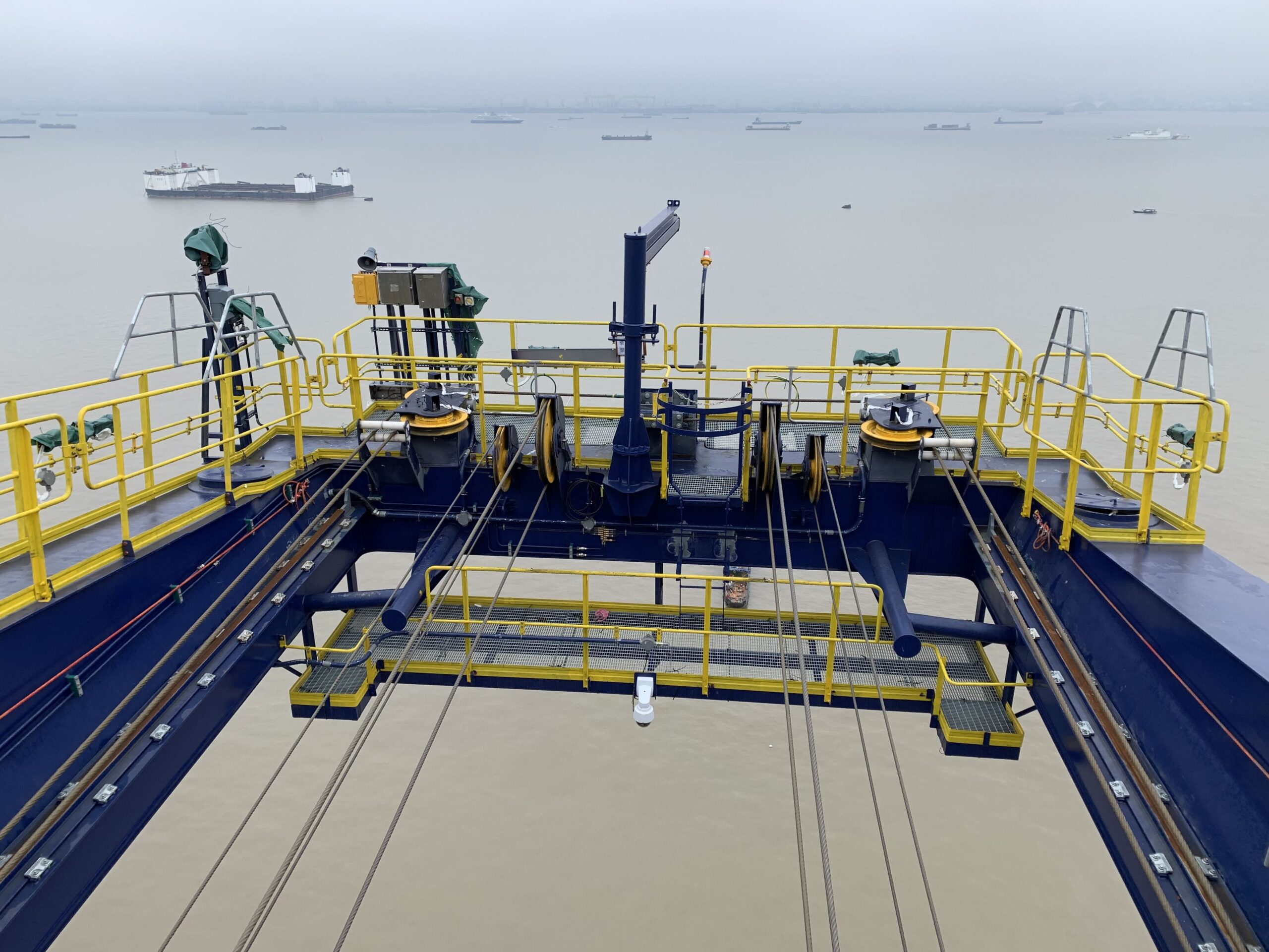
Caption: This shows a jib crane at the tip of a ship-to-shore container crane boom.
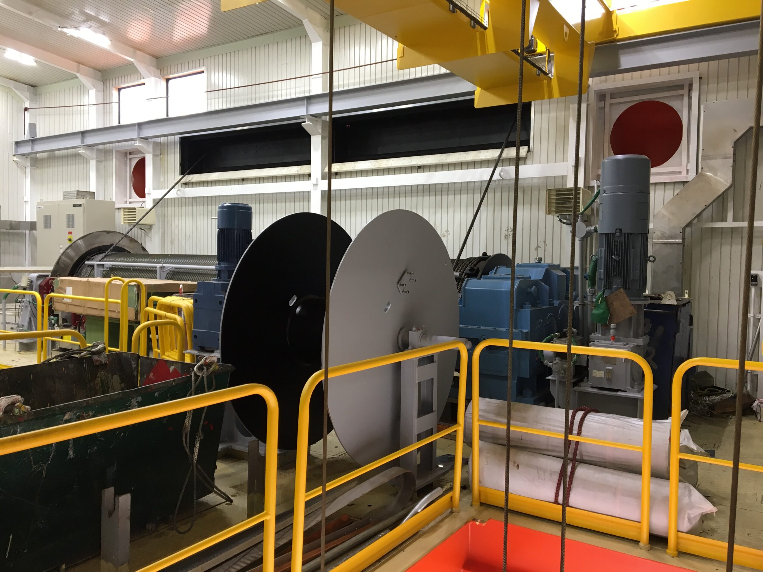
Caption: A maintenance crane being used to transfer a spool of wire rope to a machinery house for re-reeving.
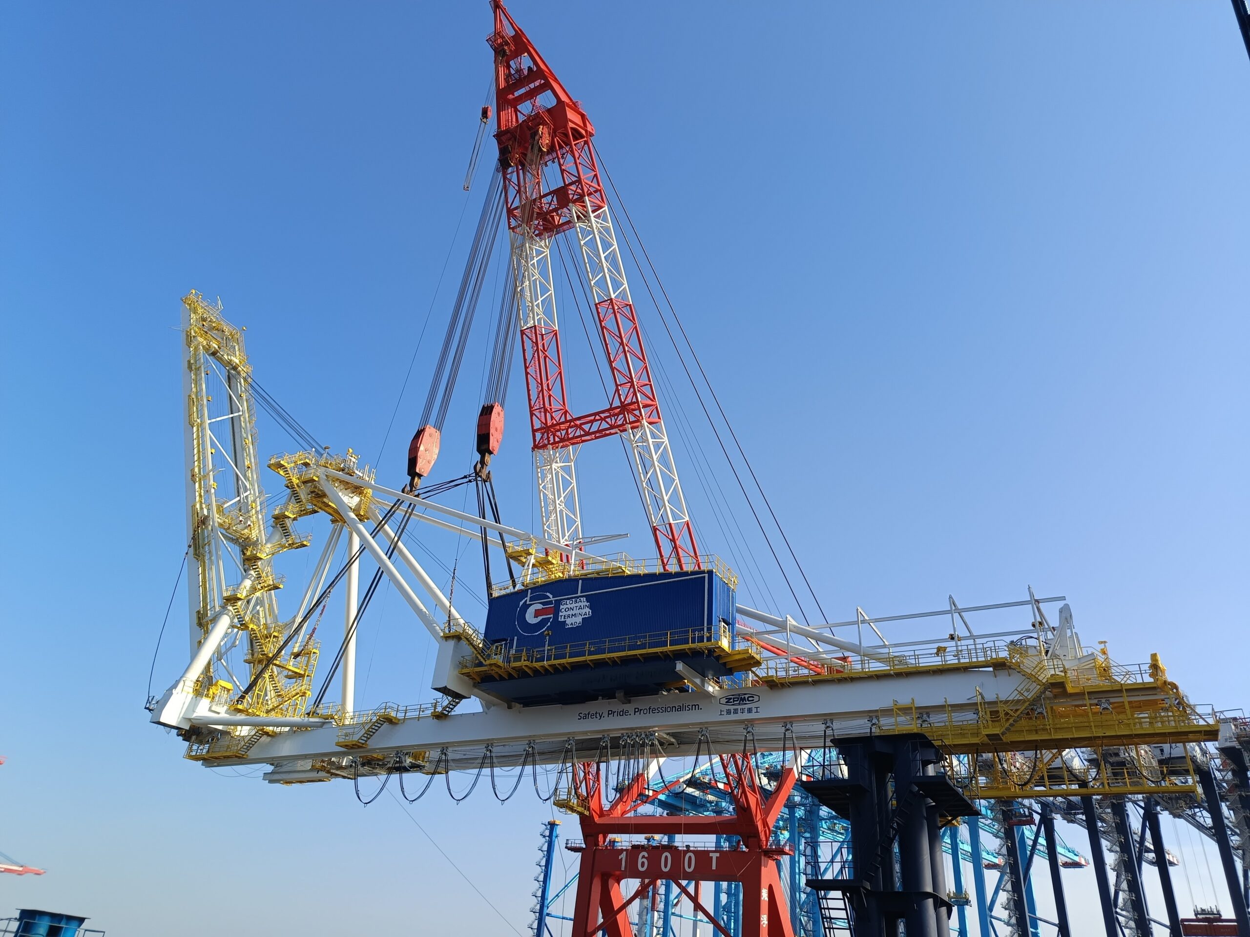
Caption: A floating crane being used to lift a container crane, which has an overhead service crane inside the blue machinery house.
Contact for editorial inquiries: Richard Phillips, richard@casperphillips.com


