Casper, Phillips & Associates - Globally Recognised Crane Engineering Services
Casper, Phillips & Associates Inc. (CPA) offers crane engineering, structural engineering, custom software and other specialist services, for ports and heavy-duty environments. CPA offers a wide variety of services tailored to customers’ needs, including procurement, specification, design, voyage bracing, modifications and rehabilitation, accident investigation and repair, and condition surveys.
With crane and material handling equipment design experience dating back to the 1960s, it can provide this service with speed and efficiency. In crane and load handling equipment, much of CPA’s practice is devoted to helping buyers contract for the machinery they want to own and then assist in enforcing the contract’s technical requirements so the buyer gets what the contract stipulates is to be provided.
Among CPA’s portfolio is a patented crane base anti-seismic isolation system (BASIS), created with nonlinear time history analysis (NLTHA).
Contact
Richie Philips
t: +1253 627-7400
e: casperph@cranedesign.com
w: www.casperphillips.com
The Devil is in the Detailing
Connection detailing is an underrated art form, especially on cranes, writes Richard Phillips, mechanical engineer at Casper, Phillips & Associates Inc. (CP&A).
In the crane design world, how beams are joined together is called connection detailing and getting these details right can literally make or break a crane. Besides reducing a crane’s potential for collapse, proper connection detailing can also extend a crane’s service life by up to 400%.
As we know, cranes experience their full rated load much more often than other structures, such as buildings and bridges. While an engineer might not be surprised that cranes see their rated load as often as they do, what is not so obvious is the consequences of millions of cycles at the full rated load. These consequences are known as “fatigue”. Fatigue is the term used to describe the failure of a steel member below its yield stress due to cyclic loading. By understanding fatigue and implementing fatigue design strategies and concepts, the crane engineer can go a long way in removing the “devil” from the detailing.
Poor fatigue detailing increases the risk of cracking, which can lead to sudden connection and member failures. The long-term benefits of good fatigue detailing are longer inspection intervals and less repair work, resulting in reduced maintenance and repair costs.
Smooth transfer
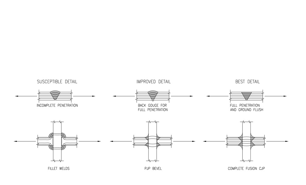
In the structural crane design world, fatigue detailing is a special class of connection design. Fatigue detailing improves the smooth transfer of loads from one beam to another by reducing stress concentrations. Stress concentrations—also called stress risers—are created when one area of a connection is more highly stressed than adjacent areas. This condition is usually the result of an abrupt change in geometry, especially around sharp corners.
Good fatigue detailing reduces stress concentrations by limiting the effects of geometry changes when connecting one beam to another. Many crane design codes address fatigue detailing by separating connection types into classes based on the severity of their stress concentrations. Historically, stress concentration factors have been found using experimental techniques though advances are being made in finite element analysis (FEA) to approximate the initiation and propagation of fatigue cracks more accurately. This is also true in many of the experimental sensors, such as strain gauges.
Modern-day technology is relevant here, as it is with everything else. The improvements of computer chips have been remarkable. They allow engineers to run very computationally demanding calculations that take a computer the same amount of time to complete as it takes for the engineer to grab a cup of coffee from the office kitchen. We can run multiple design iterations and compare results much more quickly than before. This allows engineers to consider more connection details than they could have previously. However, properly setting up and verifying the results of the FEA model is now the bottleneck.
An important complement to connection detailing is proper fabrication. On-site inspection during all phases of a crane’s construction is a must to ensure the as-designed fatigue detailing is properly implemented. Inspectors help make sure plates are properly fit-up and clean before welding. Weld inspectors review weld geometry for proper setup and carry out non-destructive testing.
Misaligned transfer
Good fatigue detailing extends to mechanical components as well. Engineers must maintain proper alignment of machinery for power transfer to occur efficiently and consistently. For a hoist-on-trolley arrangement, if the hoist machinery is not designed for the flexing of the trolley frame as the crane picks up a load, then the hoist machinery is likely to become misaligned during the pick.
At best, misaligned mechanical components are less effective—brake pads do not contact properly, leading to reduced brake torque, shafts become misaligned, leading to larger loads and accelerated wear, and gears may no longer mesh correctly—leading to shortened service life and increased maintenance costs. At worst, a coupling, gearbox, or other component can fail, putting the load at risk of dropping and requiring the crane to be immediately removed from service for costly and time-consuming repairs.
Do you know your crane?
Knowing that proper connection detailing alone can be the difference between a 10 year service life and a 40 year service life, do crane owners really “know” the life of their cranes? As a crane completes its first decade of service, do owners know the service life of their cranes and can they confidently say how much service life remains?
The answers can typically be found in the crane purchase specifications and the crane maintenance / service log. The purchase specifications state the number of moves for which the crane needs to be designed. By comparing the design moves to the actual moves in the service log, a fairly good idea of the remaining service life can be extrapolated.
Of course, this approach assumes the crane’s actual service life will meet the specified design life. However, some of these cranes have design lives of 20 years or more so it takes a long time to see if the design is successful. Sometimes design life is measured in cycles. A crane may perform over two million lifts during its useful life. If the connection designs are susceptible to cracking, the crane is more likely to have higher maintenances costs and may even fail much earlier, than a crane with proper connection detailing.
<in a box>
Tired viewpoint
Many people think of fatigue as “wearing out” of steel but this is not quite right. Fatigue failure occurs in components subjected to a high number of cycles of fluctuating stresses. Under these dynamic conditions, failure can occur at a stress level that is significantly less than that of a static load. However, if the fluctuating stresses are low enough and in an ideal environment, steel can have an infinite fatigue life.
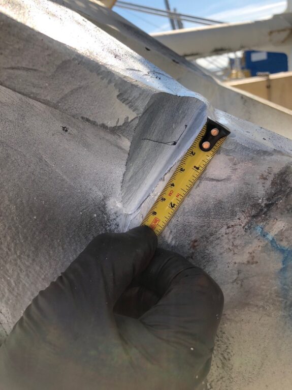
Cracks are a common mode of fatigue failure and originate from initial flaws in the steel. They can propagate from many sources, including high cycle fatigue, poor manufacturing, corrosion, and overload events such as snag, earthquake, or storm winds. The initial flaws may be microscopic or macroscopic. Growth rate increases with crack size so a flaw that has grown from microscopic to a detectable size is well along toward reaching critical size. However, if the steel lacks reasonable notch toughness (a measure of the steel’s ability to resist crack propagation), the critical crack length will be significantly smaller than a steel with excellent notch toughness.
An untrained person is unlikely to be able to visually detect the first signs of cracking and may not even recognize a substantial crack. Because of a crack’s slow growth before reaching critical size, an operator is unlikely to notice a change in the performance of the crane, even if they are very familiar with it.
<end box>

Caption: Effect of weld contour details on stress flow and fatigue behavior.

Caption: A crack appears at a welded connection.
Contact for editorial enquiries: Richard Phillips, richard@casperphillips.com


